


Internal IO A and Internal IO B Connectors
The Internal IO A and Internal IO B connectors are PHS26MRS – robust 26-pins straight shrouded 0.1" pitch flat cable headers. They provide the connections for the two sets of 10 I/O ports, 5V, and 12V power outputs.
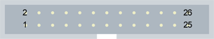
26-pin male receptacle, dual-row 2.54mm pitch, straight shrouded header
(board viewed from component side)
Internal IO A pins assignment
Pin # |
Pin name |
Usage |
1 |
GND |
Ground |
2 |
GND |
Ground |
3 |
DIN1A+ |
High-speed differential input #1 – Positive pole |
4 |
DIN1A- |
High-speed differential input #1 – Negative pole |
5 |
DIN2A+ |
High-speed differential input #2 – Positive pole |
6 |
DIN2A- |
High-speed differential input #2 – Negative pole |
7 |
IIN1A+ |
Isolated input #1 – Positive pole |
8 |
IIN1A- |
Isolated input #1 – Negative pole |
9 |
IIN2A+ |
Isolated input #2 – Positive pole |
10 |
IIN2A- |
Isolated input #2 – Negative pole |
11 |
IIN3A+ |
Isolated input #3 – Positive pole |
12 |
IIN3A- |
Isolated input #3 – Negative pole |
13 |
IIN4A+ |
Isolated input #4 – Positive pole |
14 |
IIN4A- |
Isolated input #4 – Negative pole |
15 |
IOUT1A+ |
Isolated contact output #1 – Positive pole |
16 |
IOUT1A- |
Isolated contact output #1 – Negative pole |
17 |
IOUT2A+ |
Isolated contact output #2 – Positive pole |
18 |
IOUT2A- |
Isolated contact output #2 – Negative pole |
19 |
IOUT3A+ |
Isolated contact output #3 – Positive pole |
20 |
IOUT3A- |
Isolated contact output #3 – Negative pole |
21 |
IOUT4A+ |
Isolated contact output #4 – Positive pole |
22 |
IOUT4A- |
Isolated contact output #4 – Negative pole |
23 |
+5V |
+5V Power output |
24 |
+5V_RTN |
Ground |
25 |
+12V |
+12V Power output |
26 |
+12V_RTN |
Ground |
Internal IO B pins assignment
Pin # |
Pin name |
Usage |
1 |
GND |
Ground |
2 |
GND |
Ground |
3 |
DIN1B+ |
High-speed differential input #1 – Positive pole |
4 |
DIN1B- |
High-speed differential input #1 – Negative pole |
5 |
DIN2B+ |
High-speed differential input #2 – Positive pole |
6 |
DIN2B- |
High-speed differential input #2 – Negative pole |
7 |
IIN1B+ |
Isolated input #1 – Positive pole |
8 |
IIN1B- |
Isolated input #1 – Negative pole |
9 |
IIN2B+ |
Isolated input #2 – Positive pole |
10 |
IIN2B- |
Isolated input #2 – Negative pole |
11 |
IIN3B+ |
Isolated input #3 – Positive pole |
12 |
IIN3B- |
Isolated input #3 – Negative pole |
13 |
IIN4B+ |
Isolated input #4 – Positive pole |
14 |
IIN4B- |
Isolated input #4 – Negative pole |
15 |
IOUT1B+ |
Isolated contact output #1 – Positive pole |
16 |
IOUT1B- |
Isolated contact output #1 – Negative pole |
17 |
IOUT2B+ |
Isolated contact output #2 – Positive pole |
18 |
IOUT2B- |
Isolated contact output #2 – Negative pole |
19 |
IOUT3B+ |
Isolated contact output #3 – Positive pole |
20 |
IOUT3B- |
Isolated contact output #3 – Negative pole |
21 |
IOUT4B+ |
Isolated contact output #4 – Positive pole |
22 |
IOUT4B- |
Isolated contact output #4 – Negative pole |
23 |
+5V |
+5V Power output |
24 |
+5V_RTN |
Ground |
25 |
+12V |
+12V Power output |
26 |
+12V_RTN |
Ground |