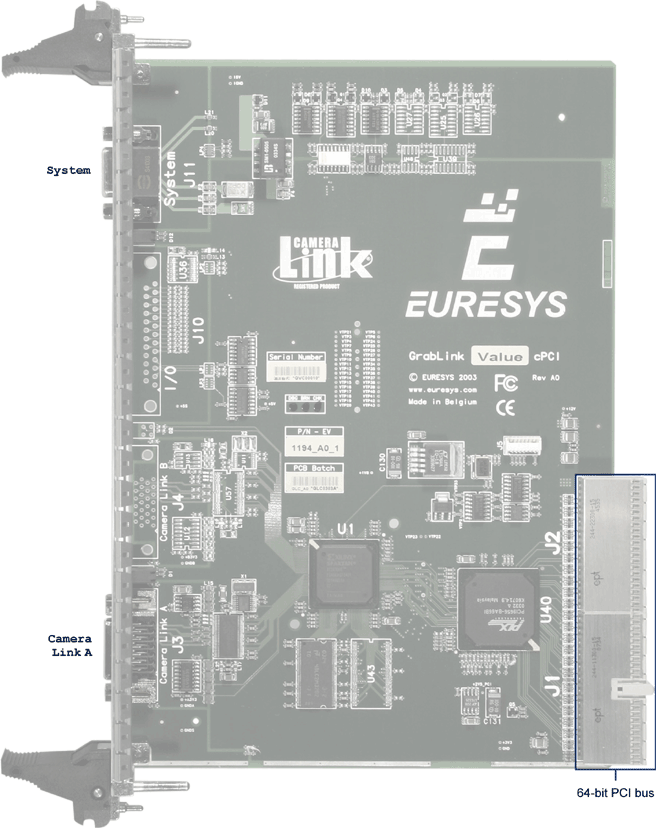
Board and Bracket Layout (cPCI)
Board Layout

Grablink Value cPCI board layout
Bracket Layout
Connectors
The bracket attached to Grablink Value cPCI provides 2 connectors.
- The upper connector is for system connection, such as external trigger, illumination control or motion encoder. It is a sub-D 9-pin female connector. This connector is called System.
- The lower connector is for camera connection. It is a blade contact high-density 26-pin female connector. It complies with the Camera Link standard. Grablink Value cPCI fully supports the Base configuration as per the standard. This connector is called Camera Link A.
LEDs
A pair of red/green LEDs placed under the System connector shows the global status of the frame grabber.
- When the green LED is lighting —ON—, MultiCam is correctly started.
- If the red LED is lighting —ON—, a board-wide error appeared.
A pair of red/green LEDs placed above the Camera Link A connector, shows information about the camera acquisition.
- The green LED is lighting —ON— during expose and readout phases of an acquisition sequence.
- If the red LED is lighting —ON—, a channel acquisition error appeared during the acquisition sequence.

Grablink Value cPCI bracket layout


