How to Connect Horizontal and Vertical References?
Connecting a TTL horizontal or vertical reference
Consider the case of a camera delivering the reference signals in TTL compliant format.
The present recommendation yields the best signal integrity as well as the best electromagnetic compatibility performance.
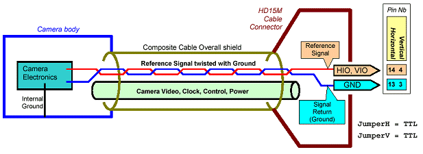
The adequate jumper configuration corresponds to the strapping involved when JumperH and JumperV are valued TTL.
Refer to the following simplified electrical drawing.

This drawing shows that the TTL reference signal coming from the camera is adequately transported by means of a twisted pair of wires. One wire transports the TTL signal, the other one is a ground connection.
The ground connection should imperatively be established at both connectors (camera side and board side).
Using a shielded or coaxial cable instead of the twisted pair is allowed, and even should be preferred when feasible.
The video cables and other control lines linking the camera to the board are preferably grouped into a single composite cable, equipped with an overall shield.
The overall shield is electrically connected to the camera body through the conductive camera connector. On the board side, the overall shield is connected to the HD15M conductive shell.
Connecting a RS-422 or LVDS horizontal or vertical reference
Consider the case of a camera delivering the reference signals in true differential format with enough strength to feed a 100Ω terminated line. RS-422 and LVDS standards are such cases.
The present recommendation yields the best signal integrity as well as the best electromagnetic compatibility performance.
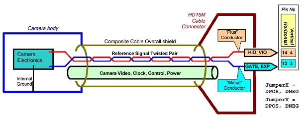
The adequate jumper configuration corresponds to the strapping involved when JumperH and JumperV are valued DPOS or DNEG.
Refer to the following simplified electrical drawing.

This drawing shows that the differential reference signal coming from the camera should be transported by means of a twisted pair line. The best situation corresponds to a pair with a 100Ω differential characteristic impedance.
The video cables and other control lines linking the camera to the board are preferably grouped into a single composite cable, equipped with a mandatory overall shield.
The overall shield is electrically connected to the camera body through the conductive camera connector. On the board side, the overall shield is connected to the HD15M conductive shell.


