How to Deliver Power Supply to the Camera?
This topic describes the recommended way to supply voltage to the camera from a Domino board.
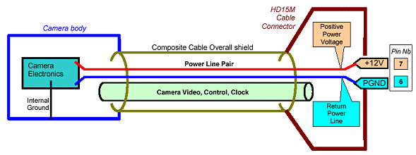
Refer to the following simplified electrical drawing.

This drawing shows that the power terminals of the camera connector should be connected to the corresponding power terminal at the camera side.
Two wires of adequate gauge should be used. The user will take into account the current consumed by the camera(s), the PC's voltage accuracy, the cable length and the camera allowed voltage range to compute the needed wire gauge.
A minimal gauge of 0.25 mm2 (AWG 23) is recommended.
The maximum current that can drawn out of the camera connector altogether is 2 A. It is recommended to limit the current to 600 mA per connector.
The power, video and other control lines linking the camera to the board are preferably grouped into a single composite cable, equipped with an overall shield.
The overall shield is electrically connected to the camera body through the conductive camera connector. On the board side, the overall shield is connected to the HD15M conductive shell.
The overall shield cannot be used as the return path for power supply.


