


Video Connectors for Picolo Alert
BNC Connectors
Picolo Alert offers four on-board BNC connectors for camera connection. They are named VIDEO1, VIDEO2, VIDEO3 and VIDEO4.
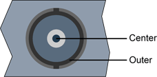
2-pin female receptacle, right-angled PCB-mount, BNC connector
(bracket viewed from outside)
VIDEO<1..4> pins assignment
Pin location |
Pin name |
Usage |
Center |
VIDEO<1..4> |
|
Outer |
GND |
Signal ground |
10-Pin Header Connectors
Picolo Alert also provides internal connectors to add up to twelve additional inputs, through Video Expansion Brackets (VEBs). They are named VEB LINK 1, VEB LINK 2 and VEB LINK 3. Each 10-pin header connector allows to connect one VEB to a Picolo Alert.
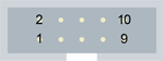
10-pin male receptacle, dual-row 2.54mm pitch, straight shrouded header
(board viewed from component side)
VEB LINK <0..4> internal headers pins assignment
Connector |
Pin # |
Pin name |
VEB LINK 0 |
1 - 2 |
VIDEO1 - GND1 |
3 - 4 |
VIDEO2- GND2 |
|
5 - 6 |
VIDEO3- GND3 |
|
7 - 8 |
VIDEO4- GND4 |
|
9 - 10 |
N.C. - Dig. GND |
|
VEB LINK 1 |
1 - 2 |
VIDEO5 - GND5 |
3 - 4 |
VIDEO6 - GND6 |
|
5 - 6 |
VIDEO7 - GND7 |
|
7 - 8 |
VIDEO8 - GND8 |
|
9 - 10 |
Presence - Dig. GND |
|
VEB LINK 2 |
1 - 2 |
VIDEO9 - GND9 |
3 - 4 |
VIDEO10 - GND10 |
|
5 - 6 |
VIDEO11 - GND11 |
|
7 - 8 |
VIDEO12 - GND12 |
|
9 - 10 |
Presence - Dig. GND |
|
VEB LINK 3 |
1 - 2 |
VIDEO13 - GND13 |
3 - 4 |
VIDEO14 - GND14 |
|
5 - 6 |
VIDEO15 - GND15 |
|
7 - 8 |
VIDEO16 - GND16 |
|
9 - 10 |
Presence - Dig. GND |
Notes
- Each video differential pair is composed of VIDEOn and GNDn, both connected to digitizer n, where n is 1, 2, 3 or 4.
- To inform the system of the VEB LINK header usage, pin 9 named Presence with pin 10 named Dig. GND must be connected. VEBs include this connection.
Moreover, Picolo Alert offers an additional internal connector named VEB LINK 0. This 10-pin header connector is mounted in parallel with the four video inputs (VIDEO1, VIDEO2, VIDEO3 and VIDEO4) available on the board bracket.