


Pixel Clock
Pixel Clock Connector Locations
When the digital synchronization is used, the camera channel generates a clock signal. The video signal is synchronized with this clock signal.
HD15F connector locations for the pixel clock
Pixel Clock Path |
Constitutive Signals |
Pin |
Connector |
Clock X |
XCK+ |
9 |
X |
XCK- |
10 |
||
GND |
3 |
The GND connection is used in case of single-ended clock sensing.
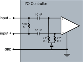
Non-Inverted Differential Pixel Clock (Default Setting)
This configuration is used with a non-inverted differential pixel clock signal. The pixel clock is applied to CK+ and CK-.
The MultiCam parameter JumperCK is set to CKDPOS and the electrical equivalent schematics is:

Equivalent schematics for CKDPOS
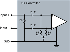
Inverted Differential Pixel Clock
This configuration is used with an inverted differential pixel clock signal. The pixel clock is applied to CK+ and CK-.
The MultiCam parameter JumperCK is set to CKDNEG and the electrical equivalent schematics is:
Equivalent schematics for CKDNEG
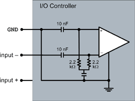
Non-Inverted Single-Ended Pixel Clock
This configuration is used with a non-inverted single-ended pixel clock signal. The pixel clock is applied to CK+ and GND.
The MultiCam parameter JumperCK is set to CKSPOS and the electrical equivalent schematics is:
Equivalent schematics for CKSPOS
Inverted Single-Ended Pixel Clock
This configuration is used with an inverted single-ended pixel clock signal. The pixel clock is applied to CK- and GND.
The MultiCam parameter JumperCK is set to CKSNEG and the electrical equivalent schematics is:
Equivalent schematics for CKSNEG
No Pixel Clock
If the camera does not use a pixel clock, the CK jumper block is empty with no jumper installed.
The JumperCK parameter is set to EMPTY and the electrical equivalent schematics is: