


Horizontal and Vertical References
Horizontal and Vertical Reference Connectors Location
When the digital synchronization is used, the camera channel generates a horizontal and vertical reference signal on individual digital lines. The video signal is synchronized with these signals.
HD15F connector locations for the horizontal and vertical reference paths
Horizontal Reference |
Single-Ended |
Differential |
||
Constitutive Signals |
Pin |
Constitutive Signals |
Pin |
|
Horizontal Sense X |
HIO |
14 |
HIO |
14 |
GND |
13 |
GATE |
15 |
|
Vertical Sense X |
VIO |
4 |
VIO |
4 |
GND |
13 |
EXP |
5 |
|
TTL Input/Output (Default Setting)
This configuration is used to control HIO and VIO signals as 2 TTL I/O lines. The direction and polarity of these two signals is determined through relevant MultiCam parameters.
The MultiCam parameter JumperH and JumperV are set to TTL and the electrical equivalent schematics is:
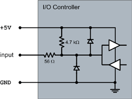
Equivalent schematics for TTL
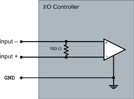
Non-Inverted Differential Horizontal Reference
This configuration is used to control HIO and VIO pins as a single non-inverted differential input line.
The positive line is connected to the HIO and VIO pin and the negative line is connected to the GATE and EXP pin.
The MultiCam parameter JumperH and JumperV are set to DPOS and the electrical equivalent schematics is:

Equivalent schematics for DPOS
Inverted Differential Horizontal Reference
This configuration is used to control HIO and VIO pins as a single inverted differential input line.
The positive line is connected to the GATE and EXP pin and the negative line is connected to the HIO and VIO pin.
The MultiCam parameter JumperH and JumperV are set to DNEG and the electrical equivalent schematics is:
Equivalent schematics for DNEG