


System Connector
This board offers multiple I/O lines with different electrical interfaces. These I/O lines are available outside the computer through the System HD-26 connector placed on the board bracket. The same I/O lines are also available on the board inside the computer through the System internal header.
System Connector
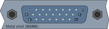
High-density 26-pin male sub-D connector
(bracket viewed from outside)
System connector pins assignment
Pin # |
Pin name |
Usage |
1 |
STA+ |
|
2 |
STA- |
|
3 |
- |
Not connected |
4 |
- |
Not connected |
5 |
Enhanced IO1 |
|
6 |
Enhanced IO2 |
|
7 |
Enhanced IO3 |
|
8 |
Enhanced IO4 |
|
9 |
GND |
Signal ground |
10 |
TRA1+ |
|
11 |
TRA2+ |
|
12 |
- |
Not connected |
13 |
- |
Not connected |
14 |
Iso+5V |
|
15 |
IsoA1 |
|
16 |
- |
Not connected |
17 |
PGND |
|
18 |
+12V |
|
19 |
TRA1- |
|
20 |
TRA2- |
|
21 |
- |
Not connected |
22 |
- |
Not connected |
23 |
IsoGND |
|
24 |
IsoA2 |
|
25 |
- |
Not connected |
26 |
+5V |
|
System Internal Header
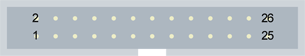
26-pin male receptacle, dual-row 2.54mm pitch, straight shrouded header
(board viewed from component side)
System header pins assignment
Pin # |
Pin name |
Usage |
1 |
TRA1+ |
|
2 |
TRA1- |
|
3 |
TRA2+ |
|
4 |
TRA2- |
|
5 |
- |
Not connected |
6 |
- |
Not connected |
7 |
- |
Not connected |
8 |
- |
Not connected |
9 |
STA+ |
|
10 |
STA- |
|
11 |
- |
Not connected |
12 |
- |
Not connected |
13 |
Iso+5V |
|
14 |
IsoGND |
|
15 |
IsoA1 |
|
16 |
IsoA2 |
|
17 |
- |
Not connected |
18 |
- |
Not connected |
19 |
Enhanced IO1 |
|
20 |
GND |
Signal ground |
21 |
Enhanced IO2 |
|
22 |
GND |
Signal ground |
23 |
Enhanced IO3 |
|
24 |
GND |
Signal ground |
25 |
Enhanced IO4 |
|
26 |
GND |
Signal ground |
For I/O electrical specifications, see DC/AC Characteristics.
For the operations of I/O lines, see I/O Operation.