Board Topologies
A topology describes the static assignment of cameras to the frame grabber connectors.
The topology used in the application is declared by the user with the MultiCam parameter BoardTopology at the beginning of the application code before creating any channel.
If the application does not use all the board resources, the user must select a topology that encompasses the needed connectivity.
The value of the BoardTopology parameter is a set of codes separated by an underscore, indicating the kind of camera linked to the connectors.
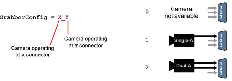
Declaring a topology
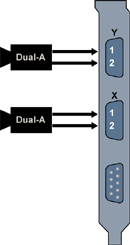
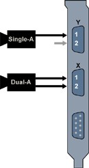
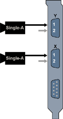
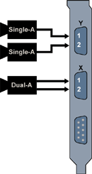
There are 6 different topologies to completely support the Domino Alpha 2 capabilities.
Out of these topologies, 3 use 1 camera per connector.
|
|
|
Topology 2-2 |
Topology 2-1 |
Topology 1-1 |
Topologies with Non-Split Cables
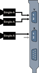
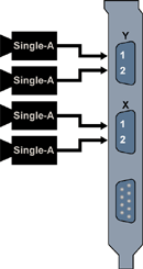
Out of the 6 available topologies, 3 use 2 cameras per connector.
|
|
|
Topology 2-11 |
Topology 1-11 |
Topology 11-11 |
Topologies with Split Cables
MultiCam Parameters
- The BoardTopology parameter is set according to the following tables.
Single channel cameras only
Application Requirement |
Recommended connectors |
||||
1 Single-A camera |
1-1 |
Y |
Single-A |
||
X |
None |
||||
2 Single-A cameras |
Y |
Single-A |
|||
X |
Single-A |
||||
Dual channel cameras only
Application Requirement |
Recommended connectors |
||||
1 Dual-A camera |
2-2 |
Y |
Dual-A |
||
X |
None |
||||
2 Dual-A cameras |
Y |
Dual-A |
|||
X |
Dual-A |
||||
Mix of dual channel and single channel cameras
Application Requirement |
Recommended connectors |
||||
1 Dual-A camera |
2-1 |
Y |
Dual-A |
||
1 Single-A camera |
X |
Single-A |
|||
Single channel cameras only, split cables allowed
Application Requirement |
Recommended connectors |
||||
3 Single-A cameras |
11-11 |
Y |
2 x Single-A |
||
X |
1 x Single-A |
||||
4 Single-A cameras |
Y |
2 x Single-A |
|||
X |
2 x Single-A |
||||
Mix of dual channel and single channel cameras, split cables allowed
Application Requirement |
Recommended Connectors |
||||
1 Dual-A camera |
2-11 |
Y |
2 x Single-A |
||
2 Single-A camera |
X |
Dual-A |
|||


