


System Connectors
Domino Symphony is equipped with a high-density 26-pin male sub-D connector and an internal 26-pin header named System for I/O and system connection.
System Connector
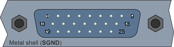
High-density 26-pin male sub-D connector
(bracket viewed from outside)
System connector pins assignment
Pin # |
Pin name |
Usage |
1 |
IO1 |
General-purpose I/O line 1 |
2 |
GND |
Signal ground |
3 |
IO2 |
General-purpose I/O line 2 |
4 |
GND |
Signal ground |
5 |
IO3 |
General-purpose I/O line 3 |
6 |
GND |
Signal ground |
7 |
IO4 |
General-purpose I/O line 4 |
8 |
GND |
Signal ground |
9 |
+5V |
5V power supply |
10 |
TRA+ |
Differential trigger input for camera A |
11 |
TRB+ |
Differential trigger input for camera B |
12 |
TRC+ |
Differential trigger input for camera C |
13 |
TRD+ |
Differential trigger input for camera D |
14 |
STA+ |
Opto-isolated strobe output for camera A |
15 |
STB+ |
Opto-isolated strobe output for camera B |
16 |
STC+ |
Opto-isolated strobe output for camera C |
17 |
STD+ |
Opto-isolated strobe output for camera D |
18 |
PGND |
Power ground |
19 |
TRA- |
Differential trigger input for camera A |
20 |
TRB- |
Differential trigger input for camera B |
21 |
TRC- |
Differential trigger input for camera C |
22 |
TRD- |
Differential trigger input for camera D |
23 |
STA- |
Opto-isolated strobe output for camera A |
24 |
STB- |
Opto-isolated strobe output for camera B |
25 |
STC- |
Opto-isolated strobe output for camera C |
26 |
STD- |
Opto-isolated strobe output for camera D |
System Internal Header
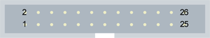
26-pin male receptacle, dual-row 2.54mm pitch, straight shrouded header
(board viewed from component side)
System header pins assignment
Pin # |
Pin name |
Usage |
1 |
IO4 |
General-purpose I/O line 4 |
2 |
GND |
Signal ground |
3 |
IO3 |
General-purpose I/O line 3 |
4 |
GND |
Signal ground |
5 |
IO2 |
General-purpose I/O line 2 |
6 |
GND |
Signal ground |
7 |
IO1 |
General-purpose I/O line 1 |
8 |
GND |
Signal ground |
9 |
STD+ |
Opto-isolated strobe output for camera D |
10 |
STD- |
Opto-isolated strobe output for camera D |
11 |
STC+ |
Opto-isolated strobe output for camera C |
12 |
STC- |
Opto-isolated strobe output for camera C |
13 |
STB+ |
Opto-isolated strobe output for camera B |
14 |
STB- |
Opto-isolated strobe output for camera B |
15 |
STA+ |
Opto-isolated strobe output for camera A |
16 |
STA- |
Opto-isolated strobe output for camera A |
17 |
TRD+ |
Differential trigger input for camera D |
18 |
TRD- |
Differential trigger input for camera D |
19 |
TRC+ |
Differential trigger input for camera C |
20 |
TRC- |
Differential trigger input for camera C |
21 |
TRB+ |
Differential trigger input for camera B |
22 |
TRB- |
Differential trigger input for camera B |
23 |
TRA+ |
Differential trigger input for camera A |
24 |
TRA- |
Differential trigger input for camera A |
25 |
GND |
Signal ground |
26 |
GND |
Signal ground |
Electrical connection of TRx+ and TRx- (x = A, B, C or D) pins depends on the selected electrical style.
- When the electrical style is differential (LVDS, RS485, DTTL), the signal has to be connected between the TRx+ and TRx- pins.
- When the electrical style is single-ended (TTL, TTLPD, 12V), the signal has to be connected between the TRx+ and the GND pins.
See I/O Operation for the operation of I/O lines.