


Digital Input Mode
To be used as digital input, the circuit is set in State U (Pull Up) and remains in this state.
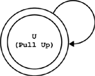
Digital input state
If this is the default state, there are no state transitions when setting digital input mode after power ON or FPGA boot sequence.
The input is tied to the I5V through a 3 kΩ pull-up resistor; this ensures a HIGH sensed level when left unconnected.
The sensing device is equipped with a Schmitt-trigger circuit. It is capable of transforming slowly changing input signals into sharply defined, glitch-free output signals:
Input voltage |
Sensed digital level |
Above positive-going threshold |
HIGH |
Below negative going threshold |
LOW |
Between thresholds |
The previously sensed level remains unchanged. |
Note. I5V stands for Isolated 5 Volt.