Isolated Current-Sense Inputs
Characteristics

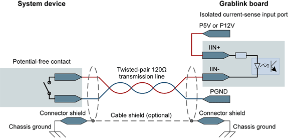
Isolated current-sense inputs (simplified schematic)
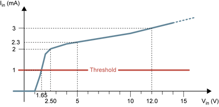
Input current vs. input voltage
The isolated current-sense input ports have the following characteristics:
- Current-sense input
- Input current threshold: 1 mA, not adjustable
- Input voltage threshold: 1.65 V, adjustable using an external resistor
- Maximum low-level input voltage: 1.5 V (over 0° ~70°C temperature range)
- Minimum high-level input voltage: 1.9 V (over 0° ~70°C temperature range)
- Current limitation at 5 mA for any input voltage up to 30 V
- Polarized input, protected in case of polarity reversal
- Accepts forward and reverse input voltage up to 30 V without damage
- Galvanic isolation
- each input is individually isolated
- isolation voltage: 500 VAC RMS
- Minimum pulse width: 10 microseconds
- Maximum pulse rate: 50 kHz
- Guaranteed 'LOW' input state when unconnected
The state of the port is reported through the InputState MultiCam parameter.
Compatible Drivers
The following drivers are compatible with the isolated current-sense inputs:
- Totem-pole LVTTL, TTL, 5V CMOS drivers
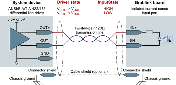
- RS-422 differential line drivers
- Potential free contact, solid-state relay, or opto-couplers. Such drivers require a user-supplied power source. No external resistors are required. The +5V and +12V power supplies available on SYSTEM IO connectors are used for connecting the inputs.
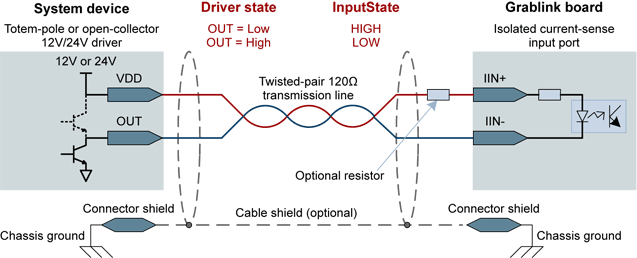
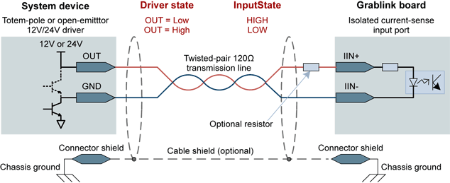
- 12V and 24V signaling voltages are also accepted. To obtain the best noise immunity with 12V and 24V signaling, it is recommended to insert a series resistor in the circuit. The recommended resistor values are 4.7 kΩ for 12V signaling and 10 kΩ for 24V signaling. Operation without series resistor is also allowed. This is sub-optimal in terms of noise immunity since the threshold remains unchanged. This drawback is alleviated by the usage of relatively low impedances.
Electrical Circuits Examples
3V3 or 5V Logic Drivers
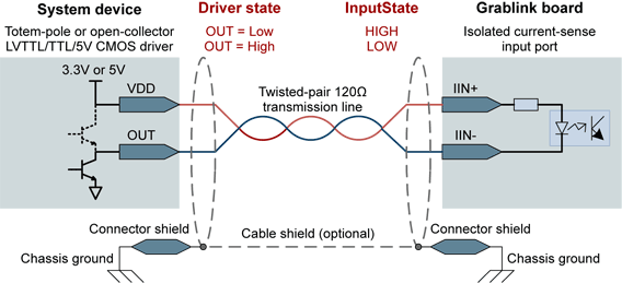
The following figure shows the wiring diagram for a system device using totem-pole (or open-collector) 3.3V low-voltage TTL, 5V TTL, or 5V CMOS drivers. With this circuit diagram, the highest transistor of the totem-pole driver is useless.
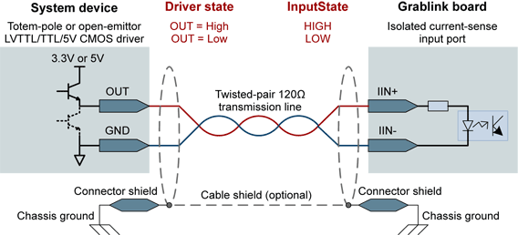
The following figure shows the wiring diagram for a system device using totem-pole (or open-emittor) 3.3V low-voltage TTL, 5V TTL, or 5V CMOS drivers. With this circuit diagram, the lowest transistor of the totem-pole driver is useless.
The following figure shows an alternate wiring diagram for a system device using RS-422 differential drivers. This alternate solution has to be used when no more high-speed differential input ports are available and when the pulse width of the transmitted signals exceeds or equal 5 microseconds:
12V or 24V Logic Drivers
The following figure shows the wiring diagram for a system device using totem-pole (or open-collector) 12V, or 24V CMOS drivers. With this circuit diagram, the highest transistor of the totem-pole driver is useless.
The following figure shows the wiring diagram for a system device using totem-pole (or open-emittor) 12V, or 24V CMOS drivers. With this circuit diagram, the lowest transistor of the totem-pole driver is useless.
Notes
For the two above circuits:
- Operation without series resistor is allowed due to the current limiting function of the input ports.
- Better noise immunity is obtained by inserting a series resistor in the circuit. The recommended resistor values are: 4.7 kΩ for 12V signaling and 10 kΩ for 24V signaling.
Potential-Free Contacts
The following figure shows the wiring diagram for a system device using potential-free contacts. In this circuit, the current is supplied by the board.
