Board and Bracket Layout (PCI)
Board Layout

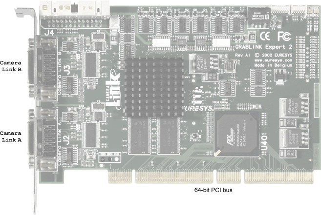
GRABLINK Expert 2 (PCI) board layout

GRABLINK Expert 2 PCI auxiliary bracket board layout
Bracket Layout
The interconnection structure of Grablink Expert 2 (PCI) uses 2 brackets.
The bracket attached to Grablink Expert 2 PCI provides 2 connectors.
- They are both for camera connection. They are blade contact high-density 26-pin female connectors. They comply with the Camera Link standard.
- The upper connector is called Camera Link B, while the lower one is called Camera Link A. Grablink Expert 2 fully supports the Base and Medium configurations as per the standard. In the medium configuration, the Camera Link A connector is used as the primary connector while the Camera Link B connector is used as the secondary connector.

GRABLINK Expert 2 PCI bracket layout
Additional interconnection means are provided on a separate card bracket. It is attached to an auxiliary board linked to Grablink Expert 2 (PCI) by a 26-wire ribbon cable.
The auxiliary bracket provides 2 connectors.
- The upper connector is for general purpose Input/Output connection. It is a sub-D 25-pin female connector called I/O.
- The lower connector is for system connection, such as external trigger, illumination control or motion encoder. It is a sub-D 9-pin female connector called SYSTEM.

GRABLINK Expert 2 PCI auxiliary bracket layout


