


Board and Bracket Layout
Board Layout
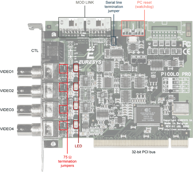
Picolo Pro 3 board layout
Each additional internal Module Pro 3 adds 4 video inputs to a Picolo Pro 3.
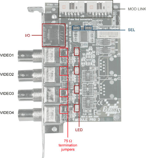
Module Pro 3 board layout
One unique additional internal Module 12 Pro 3 allows to connect 12 video inputs to a Picolo Pro 3, using only one blind slot. With regard to video inputs, this board replaces 3 Modules Pro 3.
Moreover, up to five MIO Modules can be added to a Picolo Pro 3 with 1 Module 12 Pro 3.
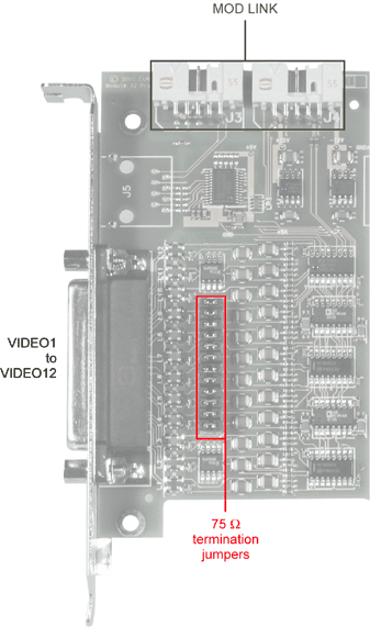
Module 12 Pro 3 board layout
Bracket Layout
The bracket attached to Picolo Pro 3 provides five connectors.
The upper connector is for I/O lines. It is a RJ-45 female connector. This connector is called CTL.
The four other connectors are for camera connection. They are selectable color or monochrome composite inputs. These BNC connectors are called, from top to bottom, VIDEO1, VIDEO2, VIDEO3 and VIDEO4.
The bracket attached to Module Pro 3 is exactly the same than the Picolo Pro 3 one.
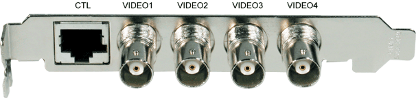
Picolo Pro 3 and Module Pro 3 bracket layout
The bracket attached to Module 12 Pro 3 provides one connector. It is a sub-D 25-pin female connector. This connector is called VIDEO1 to VIDEO12.
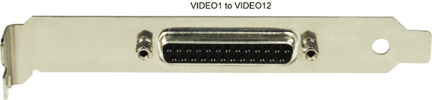
Module 12 Pro 3 bracket layout