


Board and Bracket Layout
Board Layout
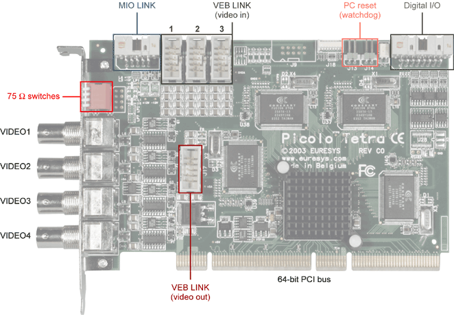
Picolo Tetra board layout
Bracket Layout
The bracket attached to Picolo Tetra provides four BNC connectors and a block of four 75Ω switches.
The four BNC connectors are for camera connection. They are selectable color or monochrome composite inputs, terminated with removable 75Ω resistors. These connectors are called, from top to bottom, VIDEO1, VIDEO2, VIDEO3 and VIDEO4.
The switch n (with n = 1, 2, 3 or 4) controls the 75Ω termination of the corresponding VIDEOn input. In the factory configuration, all video terminations are active; all switches are closed (ON position). To remove the termination, set the switch to the OFF position.
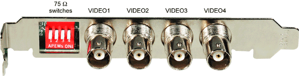
Picolo Tetra bracket layout