Line-Scan Camera and System Relationship
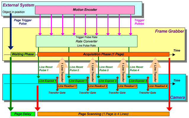
The following figure is a conceptual view of the task that an industrial frame grabber is in charge of. A line-scan camera and some part of the external system are considered.
This drawing addresses the most complex case. It may happen that the actual application involves only a part of the figured resources.

At any time, the frame grabber controls the line sequencing of the camera. To achieve this, a succession of line-reset pulses is sent to the camera at a frequency proportional to the repetition frequency of a succession of trigger pulses sent by a motion encoder. This is the effect of the built-in rate converter.
The external system determines that a moving object is about to reach the camera field of view. The position detector can be located well in front of the actual observed line. A page trigger pulse is issued to inform the frame grabber on this instant.
As a reaction, the frame grabber enters a programmable delay, called the page delay. This page delay can be expressed as a number of scan lines. At the end of the page delay, the object to be scanned effectively enters the field of view.
The page delay corresponds to the waiting phase inside the frame grabber. Following the waiting phase, the acquisition phase takes place. The rationale for the acquisition phase is to bring a video page from the camera into the frame grabber.
The page is made of a number of video lines. At each line, an intense data transfer takes place to transport data from the camera into the frame grabber. Each transfer corresponds to the readout condition for the camera.
When all the lines are elapsed, the page is fully acquired. The frame grabber applies a rich set of data conditioning actions to the acquired image, and sends it through the peripheral bus to the host computer memory.


