


Camera Connectors
Domino Harmony is equipped with two high-density 15-pin female sub-D connectors named Camera X and Camera Y, and a internal 10-pin header named Video for cameras connection.
Camera X and Camera Y Connectors
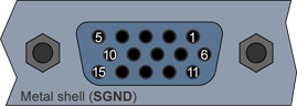
High-density 15-pin female sub-D connector
(bracket viewed from outside)
Camera X and Camera Y pins assignment
Pin # |
Pin name on Camera X |
Pin name on Camera Y |
Usage |
1 |
XV1+ |
YV1+ |
Video signal 1, inner wire |
2 |
XV1- |
YV1- |
Video signal 1, shield |
3 |
GND |
GND |
Signal ground |
4 |
XCC3 |
YCC3 |
Camera control line 3 |
5 |
XCC4 |
YCC4 |
Camera control line 4 |
6 |
PGND |
PGND |
Power ground |
7 |
+12V |
+12V |
Power voltage to camera |
8 |
XCC5 |
YCC5 |
Camera control line 5 |
9 |
XV3+ |
– |
Video signal 3, inner wire |
10 |
XV3- |
– |
Video signal 3, shield |
11 |
XV2+ |
– |
Video signal 2, inner wire |
12 |
XV2- |
– |
Video signal 2, shield |
13 |
GND |
GND |
Signal ground |
14 |
XCC1 |
YCC1 |
Camera control line 1 |
15 |
XCC2 |
YCC2 |
Camera control line 2 |
Video Internal Header
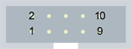
10-pin male receptacle, dual-row 2.54mm pitch, straight shrouded header
(board viewed from component side)
Video header pins assignment
Pin # |
Pin name |
Usage |
1 |
XV1+ |
Video signal 1 on connector X, inner wire |
2 |
XV1- |
Video signal 1 on connector X, shield |
3 |
XV2+ |
Video signal 2 on connector X, inner wire |
4 |
XV2- |
Video signal 2 on connector X, shield |
5 |
YV1+ |
Video signal 1 on connector Y, inner wire |
6 |
YV1- |
Video signal 1 on connector Y, shield |
7 |
XV3+ |
Video signal 3 on connector X, inner wire |
8 |
XV3- |
Video signal 3 on connector X, shield |
9 |
GND |
Signal ground |
10 |
GND |
Signal ground |
See I/O Operation for the operation of I/O lines.