


System Connector
Domino Harmony is equipped with a high-density 15-pin male sub-D connector and an internal 16-pin header named System for I/O connection.
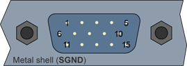
High-density 15-pin male sub-D connector
(bracket viewed from outside)
System connector pins assignment
Pin # |
Pin name |
Usage |
1 |
Enhanced IO1 |
General-purpose enhanced I/O line 1 |
2 |
Enhanced IO2 |
General-purpose enhanced I/O line 2 |
3 |
Enhanced IO3 |
General-purpose enhanced I/O line 3 |
4 |
Enhanced IO4 |
General-purpose enhanced I/O line 4 |
5 |
GND |
Signal ground |
6 |
TRX+ |
Differential trigger input for camera X |
7 |
TRY+ |
Differential trigger input for camera Y |
8 |
STX+ |
Opto-isolated strobe output for camera X |
9 |
STY+ |
Opto-isolated strobe output for camera Y |
10 |
+5V |
5V power supply |
11 |
TRX- |
Differential trigger input for camera X |
12 |
TRY- |
Differential trigger input for camera Y |
13 |
STX- |
Opto-isolated strobe output for camera X |
14 |
STY- |
Opto-isolated strobe output for camera Y |
15 |
PGND |
Power ground |

16-pin male receptacle, dual-row 2.54mm pitch, straight shrouded header
(board viewed from component side)
System header pins assignment
Pin # |
Pin name |
Usage |
1 |
TRX+ |
Differential trigger input for camera X |
2 |
TRX- |
Differential trigger input for camera X |
3 |
TRY+ |
Differential trigger input for camera Y |
4 |
TRY- |
Differential trigger input for camera Y |
5 |
STX+ |
Opto-isolated strobe output for camera X |
6 |
STX- |
Opto-isolated strobe output for camera X |
7 |
STY+ |
Opto-isolated strobe output for camera Y |
8 |
STY- |
Opto-isolated strobe output for camera Y |
9 |
Enhanced IO1 |
General purpose Enhanced I/O line 1 |
10 |
GND |
Signal ground |
11 |
Enhanced IO2 |
General-purpose enhanced I/O line 2 |
12 |
GND |
Signal ground |
13 |
Enhanced IO3 |
General-purpose enhanced I/O line 3 |
14 |
GND |
Signal ground |
15 |
Enhanced IO4 |
General-purpose enhanced I/O line 4 |
16 |
GND |
Signal ground |
See I/O Operation for the operation of I/O lines.