Introduction
This isolated I/O port has the following characteristics:
- it is digital; it delivers and/or senses 1-bit digital information
- it is isolated; it features a 500V isolation barrier
- it is bidirectional; it can be configured as an input or as an output with read back capability
- it is multimode: it can be operated as:
- isolated totem-pole digital output
- isolated open collector digital output with 3 kΩ pull-up resistor
- isolated open emitter digital output with 2 kΩ pull-down resistor
- isolated digital input with 3 kΩ pull-up resistor
- isolated high-voltage digital input with 2 kΩ pull-down resistor
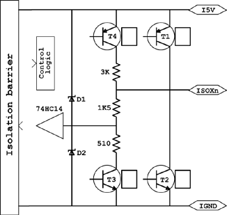
Isolated I/O port ISOXn equivalent schematic
Note. I5V stands for Isolated 5 Volt.
The isolation barrier is composed with:
- An isolated DC/DC converter delivering non-regulated 5V power to the on-board devices and, when required, to the external devices via the I5V and IGND pins.
- A set of opto-couplers for the control and data in signals.
The 74HC14 is a HCMOS 5V device that implements a Schmitt-trigger input with hysteresis. It senses the voltage on the ISOXn through a 1.5 kΩ series resistor; it is protected against over voltage by Schottky diodes D1 and D2.
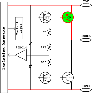
T1 connects ISOXn to I5V, forcing the ISOXn port to a HIGH level.
T2 connects ISOXn to IGND, forcing the ISOXn port to a LOW level.
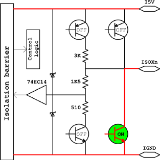
T3 connects the chain of 1.5 kΩ and 510Ω resistors to IGND. This enables a 2 kΩ pull-down resistor on ISOXn and a 1/4 voltage divider in the input sense circuit.
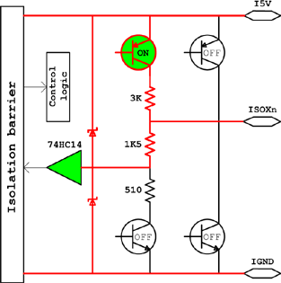
T4 connects the 3 kΩ resistor to I5V, enabling a 3 kΩ pull-up on ISOXn.
The control logic turns on one transistor at a time which leads to four possible "states" of the electrical circuit. The default state is State U (Pull Up). The circuit resets to default state at power-on or when the FPGA device is cleared.
Four states of the electrical circuit
State U (Pull Up) |
State H (Force High) |
|
|
State D (Pull Down) |
State L (Force Low) |
|
|