


High Voltage Digital Input Mode
To be used as high voltage digital input, the circuit is set in State D (Pull Down) and remains in this state.
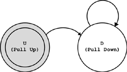
High voltage digital input state
A state transition from State U (Pull-Up) occurs when setting high voltage digital input mode after power ON or FPGA boot sequence.
The input is tied to the IGND through a 2 kΩ pull-down resistor; this ensures a LOW sensed level when left unconnected.
The sensing device receives a quarter of the input voltage; consequently, the voltage input range and the voltage thresholds are those of the digital input mode multiplied by four.
The sensing device is equipped with a Schmitt-trigger circuit. It is capable of transforming slowly changing input signals into sharply defined, glitch-free output signals:
Input voltage |
Sensed digital level |
Above positive-going threshold |
HIGH |
Below negative going threshold |
LOW |
Between thresholds |
The previously sensed level remains unchanged. |