Factory Inputs - IN1...IN4
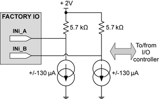
There are four professional input ports on factory I/O connector. The ports are named IN1, IN2, IN3, and IN4.

Factory Inputs
Each port has two pins named respectively INi-A and INi-B; with i = {1, 2, 3, 4}. This digital non-isolated differential input is polarity insensitive and is able to interpret TTL, high voltage and contact closure.
The I/O controller measure the impedance of the device connected across both inputs. If the impedance is above 4 kΩ, the VIOS concludes that the circuit is open and returns an OPEN state. If the impedance is below 4 kΩ, the I/O controller measures the voltage present.
If the measured voltage is above the voltage threshold (Vth), the IO controller returns a HIGH state. If the measured voltage is below Vth, the VIOS returns a LOW state. The voltage threshold Vth can take two values (1.5V and 6V).
Hint: The capability to detect an open state can be advantageously used with TTL or high voltage signaling to detect a line that is abnormally broken.
DC Specifications
Parameter |
Min |
Typ. |
Max |
Units |
Open threshold |
2 |
4 |
9 |
kΩ |
Measurement current |
|
±130 |
|
µA |
Voltage threshold (TTL) |
1 |
1.5 |
2 |
V |
Voltage threshold (12V) |
5 |
6 |
7 |
V |
Maximum differential input voltage (not operating) |
|
|
±27 |
V |
Maximum input voltage (not operating) |
-27 |
|
+27 |
V |
Input voltage range to correctly interpret OPEN/CLOSE states on contacts |
-3 |
|
+6 |
V |
Input voltage range to correctly interpret HIGH/LOW states on 5V signals |
-11 |
|
+14 |
V |
Input voltage range to correctly interpret HIGH/LOW states on 12V signals |
-11 |
|
+14 |
V |
Input voltage range to correctly interpret HIGH/LOW states on 24V signals |
-24 |
|
+26 |
V |
Common mode noise immunity from DC to 20MHz (filter set to 100ms) |
8 |
|
|
V |
AC Specifications
Parameter |
Min |
Typ. |
Max |
Units |
Input state sampling period |
|
4 |
|
ms |


