


General-Purpose Output
When configured for general-purpose usage, the output multiplexer is restricted to two positions: LOW and HIGH. The following state diagram shows the 2 states and all the possible inter-state transition:
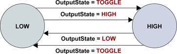
Output multiplexer state diagram (OutputFunction = SOFT)
The position of the output multiplexer is controlled by means of OutputState, a Board class MultiCam parameter belonging to the Input/Output Control category.
The "LOW" state means that the output multiplexer is in the "LOW" position. Setting OutputState to LOW forces immediately the output multiplexer to the "LOW state".
The "HIGH" state means that the output multiplexer is in the "HIGH" position. Setting OutputState to HIGH forces immediately the output multiplexer to the "HIGH state".
Setting OutputState to TOGGLE forces immediately the output multiplexer to change its position from LOW to HIGH, if it was at the LOW position or vice-versa.
I/O index assignments and specific member values of the output-related board I/O parameters
Index |
|||||
1 |
IO |
IOUT1 |
OPTO |
FREE |
UNKNOWN |
2 |
IO |
IOUT2 |
OPTO |
FREE |
UNKNOWN |
3 |
IO |
IOUT3 |
OPTO |
FREE |
UNKNOWN |
4 |
IO |
IOUT4 |
OPTO |
FREE |
UNKNOWN |
7 |
CAMERA |
CC1 |
LVDS |
FREE |
UNKNOWN |
8 |
CAMERA |
CC2 |
LVDS |
FREE |
UNKNOWN |
9 |
CAMERA |
CC3 |
LVDS |
FREE |
UNKNOWN |
10 |
CAMERA |
CC4 |
LVDS |
FREE |
UNKNOWN |
The I/O indices 0, 5, 6, and {11 24} have no output-related function.