


Input Thresholds
The four inputs are electrically isolated (by opto-coupler) from the potential of the PC case in which the Picolo board is inserted. However they are not isolated from each other.
Each input is represented by two terminals named In and InG, where n is 1, 2, 3 or 4.
An input is active when In and InG are connected. In this condition, a DC current of about 3.5 mA flows between In and InG.
An input is inactive when the contact between In and InG is open.
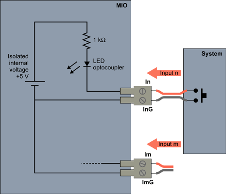
MIO Module input thresholds
The input state is displayed with 4 green LEDs: a LED is lighted when the corresponding input is active.
Vin - VinG |
Effect |
< -1 V |
Forbidden |
-1 to 1.5 V |
Active input detected |
1.5 to 10 V |
Inactive input detected |
> 10 V |
Forbidden |