


Board and Bracket Layout
Board Layout
MIO Module does not require a connection to the motherboard. However, when installed, it occupies the space of a PCI slot location.
MIO Module has to be connected to Picolo Pro 3, Picolo Tetra or another MIO Module via the MIO LINK connectors, using flat cables. See also Connecting MIO Module to Picolo Pro 3 and Connecting MIO Module to Picolo Tetra.
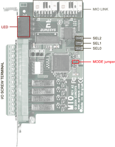
MIO Module board layout
Bracket Layout
The bracket attached to MIO Module provides a group of 8 LEDs and a removable 16-position screw terminal block.
The removable screw-terminal block collects the 8 I/O lines. Indeed, each line is available as a pair of electrical wires. This connector is called I/O SCREW TERMINAL.
The LEDs monitor the I/O line status:
- The input state is displayed with 4 green LEDs: the INn LED (where n = 1, 2, 3 or 4) is lighted when the corresponding two terminals In and InG are connected. For more details, see Input Thresholds.
- The output state is displayed with 4 orange LEDs: the OUTn LED (where n = 1, 2, 3 or 4) is lighted when the corresponding terminal OnA is connected to OnB (contact shorted). For more details, see Output Thresholds.
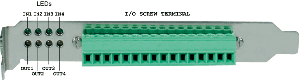
MIO Module bracket layout